| File > Load |
Loads table ordering data from a file. By default, ORD files are searched, but SYM (table symbology) files can also be read. |
| File > Save |
Saves the table ordering data to file. The file can be loaded into any new design file. This creates a binary file with ORD extension. |
| File > Import |
Imports a table ordering data file. This option does not apply to Masking. |
| No. |
Displays the criteria group number. Several criteria table lines can be grouped together so all elements matching a line in the group are printed together. Grouping is performed by the Join tool. Single lines are typically their own groups. |
| Description |
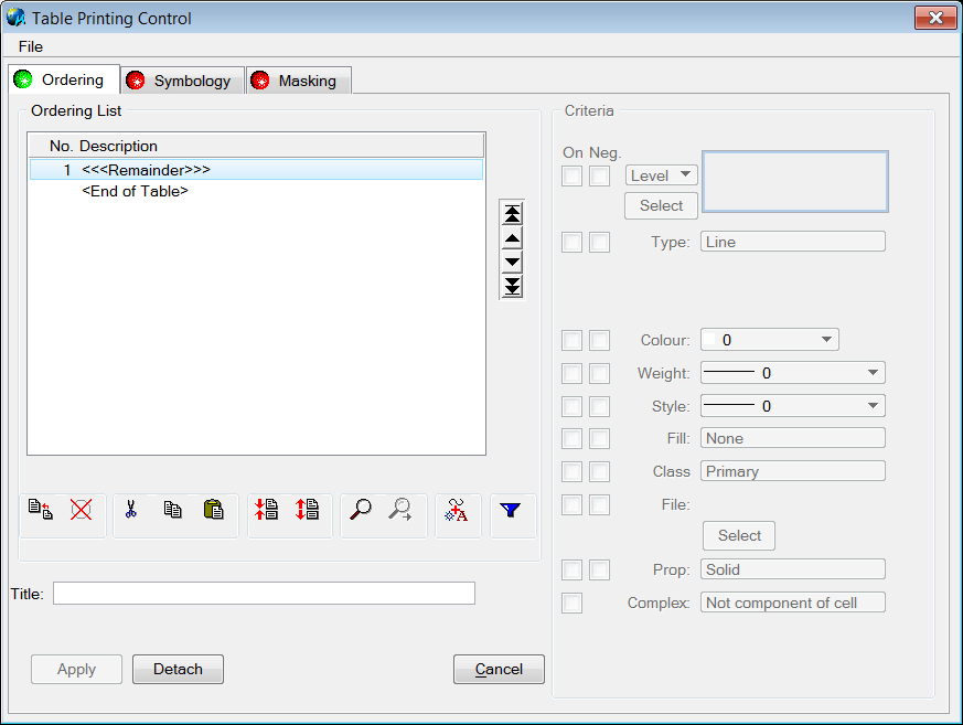
Controls the main structure of the table data. Each line in the table is defined by its description and a matching set of criteria used to group elements. Elements matching the criteria of the first line are printed last (or on top of other elements). Elements matching the last line, but not any criteria above, are printed first and appear on the bottom. Enter a description by double clicking on the line and entering a maximum of 50 characters in the Description dialog.
Two special criteria table entries appear in any table. They have no criteria and cannot be edited, removed, or copied.
- <<<Remainder>>> - if an element does not match any user defined criteria, it is printed in the position of the remainder.
- <End Of Table> - signifies the end of the table and does not affect printing.
All elements within a group are printed in the order they appear in the design file, or as they would with File Ordered Printing. For example, if the first two lines, Text (Black) and Text (Red), are joined to form group number 1, all black and red text elements are printed last (on top), if using Table Ordered Printing. Relative order between the red and black text is dependent on the file ordering for those elements.
|
| Move Arrows |

Moves a line up or down one slot, or to the top or bottom of the list. A selected line can also be moved by dragging and dropping to a different position within the table. This option does not apply to Masking.
|
| Insert |

Inserts a new blank criteria line above the currently selected line.
|
| Delete |

Removes the selected line.
|
| Cut |

Cuts the selected line, including all the matching criteria data, and places it in the clipboard.
|
| Copy |

Makes a copy of the selected line, including matching criteria data, and places it in the clipboard.
|
| Paste |

Replaces the selected line with the contents of the clipboard. Any pre-existing contents of the line are lost. To avoid this loss, insert a new line and paste clipboard contents into the empty line.
|
| Join Lines |

Combines the next criteria group with the criteria group selected, giving both the same priority for plotting in file order. This option only applies to Ordering.
Note: Filter does not work for joined lines, only for the selected single line.
|
| Split Lines |

Separates a line from its criteria group. This option only applies to Ordering.
|
| Search |

Aids in finding a line with criteria that matches an element selected in the design file. The first line with matching criteria is selected. Select this tool first, then select the element.
If an element is selected that is not defined by any criteria in the table, the Remainder entry is selected on the Ordering tab. When performed from the Symbology tab, a warning displays. This option does not apply to Masking.
|
| Search Again |

Finds subsequent lines that match the element selected when using the Search tool. This aids in finding problems with the table when more than one line matches an element or in finding situations that are not correct.
If an element is selected that is not defined by any criteria in the table, this option works the same as Search.
|
| Add Feature |

Adds a new line to the table using an element in the design file to set the initial criteria. Most criteria types are enabled when the line is created but can be edited. This option does not apply to Masking.
|
| Filter |

Changes the display to only show elements that apply to the selected line. Only one filter can be set at a time. This option does not apply to Masking.
You can use the filter results to adjust criteria until only the desired elements appear for each line. Or, by clicking Filter when Remainder is selected, you can find any elements not accounted for in Ordering and highlight possible omissions.
A new line can be selected or criteria edited while a filter is active. Update the screen by performing a MicroStation view update.
|
| Title |
Provides a unique name for a table, making tables more manageable and helping to distinguish between text files when multiple tables have been output. |
| On |
Enables the associated criteria. For example, if the Text (Black) line is selected and the Type and Colour criteria are enabled, when comparing an element against this line, the color and type of the element must match those values set in the Table Printing Control dialog to be considered a match. |
| Neg. |
Causes only elements that do not match the negated criteria to be selected. For example, if the Colour criteria is negated, elements only match with the selected line if they are not of the specified color. |
| Level/Filter |
Specifies which level the element must be on to be considered a match. When cell and shared cell elements are encountered with the Level criteria set, the cell only needs to contain one element that is on a level defined in the criteria data. When filter is selected, only elements on the levels in the MicroStation filter have their symbology modified. |
| Type |
Specifies the type of MicroStation element that can be displayed. Some options include several element types.
- Line, Curve, Arc
- B-Spline Curve (B-Spline that is not closed)
- Line String or Complex String
- All Open Elements (includes Line, Curve, Arc, B-Spline Curve, Line String, and Complex String)
- Shape
- B-Spline Shape (B-Spline element that is closed)
- Complex Shape
- Ellipse (includes circles)
- All Closed Elements (includes Shape, B-Spline Shape, Complex Shape, and Ellipse)
- Text, Text Node, All Text
- Cell, Shared Cell
- All Cells (includes Cell and Shared Cells)
- Multi-line
- Raster - Element
- Raster Manager (See For Type Raster Manager for additional information)
- Dimension
|
| Size |
Compares text element height and is considered a match if the text element is greater than or equal to the minSize but less than or equal to the maxSize. This criteria only appears if the Type is either Text or Text Node and is not negated. |
| Cell Name |
Compares cell names. This criterion only appears if the Type is either Cell or Shared Cell and is not negated. |
| Colour |
Specifies the color an element must be to match the selected line. |
| Weight |
Specifies the weight the element must be to match the selected line. |
| Style |
Specifies the style the element must be to match the selected line. |
| Fill |
Specifies if the element must be filled or not. If selected, elements that cannot be filled automatically fail to match. For example, if Fill was set to None, text elements would not match because they cannot be filled. |
| Class |
Specifies the class the element must be to match the selected line. |
| File |
Specifies the source file of the element in question whereby file 0 is the Master File and files 1-255 are reference files. Since the criteria data only stores the reference file slot number, if reference file attachments are changed, the table ordering data may no longer be valid if this criterion is used. |
| Logical |
Causes elements to be selected only from reference files that match the logical name with the string. The string can contain standard wildcard characters * and ?. Text comparison is case sensitive. |
| Prop |
Specifies element properties. |
| Complex |
Specifies if components come from cells. |
| Apply |
Attaches the data to the design file, making the table available when printing, and closes the dialog. |
| Detach |
Removes all data from the design file and closes the dialog. |
| Cancel |
Closes the dialog without storing any changes in the design. |